A stable installation guide that ticks every compliance box on paper often falls short the moment horses start using the space. That’s the everyday reality for equestrian centre owners across Australia and New Zealand—managing 10 to 40 horses, where a stall wall that bows slightly under pressure or a drainage slope that doesn’t clear wash-down water isn’t a catastrophe. It’s an ongoing maintenance headache that eats into operational time and budget, year after year. The industry talks a lot about structural engineering, but the real worry sits in the quiet things: treated pine that warps after two wet winters, kickboard fixings that loosen invisibly, or a 5mm gap between rubber mats where a shod hoof can catch.
The mistake that keeps coming up during site reviews isn’t a gross installation error—it’s choosing materials and fasteners that survive the builder’s handover but not the actual daily punishment of 600-kilo animals. Many stall kickboards, for instance, are fixed with basic coach screws into timber studs. Works fine for a few months. Then a horse leans, shifts, and the screw threads slowly chew the hole bigger. Pretty soon the board is pulling away from the wall. The fix isn’t high-tech; it’s specifying structural timber connectors rated for cyclic lateral loads and checking the pull-out values against the expected animal impact. Before signing off on a contract, ask your installer for the fastener manufacturer’s technical bulletin that covers dynamic pull-out in softwood framing. If they can’t produce it, you’re accepting a recurring maintenance liability that no paint job will cover.
Foundation & Anchoring Errors
The two costliest errors in Oceania warranty claims are not panel misalignment—they are skipped base compaction and anchors driven into topsoil instead of bearing strata.
Crushed-Rock Base Compaction: The PSI Threshold That Prevents Racking
ANZ equestrian centers consistently underestimate the compaction density required under a portable stable. A properly compacted crushed-rock base directly determines whether your bay stays square or racks out of alignment within two seasons. For a standard 3.6 m × 3.6 m bay, the substrate must achieve no less than 95% Modified Proctor density, equating to approximately 3,000–3,500 psi bearing capacity when tested with a nuclear density gauge. Anything less and differential settlement will pull panels apart at the pre-drilled connection points.
The base rock specification matters equally. Use 40 mm minus crushed aggregate with angular particles—rounded river gravel never interlocks properly. Spread the material in 100 mm lifts and compact each layer individually. A single thick lift compacted from the top will leave loose pockets at depth. The finished pad must extend a minimum of 600 mm beyond the stable footprint on all sides. This provides a working platform for the perimeter beam formwork and prevents edge erosion that undercuts the slab over time.
The Perimeter Beam: What Happens When It Gets Omitted
Skipping the perimeter beam is the fastest way to void a frame warranty. Without a continuous reinforced concrete edge beam tying the anchor points together, individual ground anchors act in isolation. When wind uplift cycles—common in AS/NZS 1170.2 Region C and D sites across coastal Queensland and New Zealand—the windward anchors gradually elongate their holes in compacted base material. The leeward side lifts incrementally. Within 12 months, you have a stable frame that moves 5–8 mm with every gust, generating the panel gaps that injure horses and admit driving rain.
A proper perimeter beam also gives your anchor system a monolithic reaction mass. The beam dimensions should be 300 mm wide × 250 mm deep with continuous N12 rebar top and bottom. Cast the beam so the top sits 50 mm above finished ground level—this prevents stormwater from flowing under the stable floor and keeps the HDPE bottom rails dry during heavy ANZ rainfall events.
6-Point Anchor System: The Installation Sequence That Transfers 10 kN Uplift
DB Stable’s 6-point anchor system delivers 10 kN uplift resistance per bay, tested to AS/NZS 1170.2 wind loads for Regions C and D. The test data was generated using 316 stainless steel M16 chemical-set anchors cast into a C25 concrete perimeter beam at 28-day cure. The sequence of installation is non-negotiable to achieve the rated capacity.
Start with the four corner anchors. Position each anchor bracket so the mounting slot aligns with the pre-drilled hole in the galvanized corner column base plate. Torque to 65 N·m. Do not tighten the two mid-span anchors until all four corners are seated. This prevents the frame from being pulled out of square during tensioning. Once the corners are locked, install the mid-span anchors on opposing sides simultaneously, torquing in 20 N·m increments until both reach the 65 N·m specification. The paired tightening eliminates frame twist. After 72 hours of curing under normal ANZ ambient temperatures (15–25°C), re-torque all six anchors to 65 N·m to compensate for any creep relaxation in the epoxy.
The chemical-set anchor specification is equally critical. Use a pure epoxy formulation rated for saturated concrete conditions—the perimeter beam will be wet during extended rainy seasons. Polyester resin anchors lose up to 40% of their bond strength in damp substrate. The hole must be drilled 10 mm deeper than the anchor embedment depth, then blown out twice with a hand pump and brushed once with a nylon bore brush. Residual drilling dust is the silent killer of pull-out strength in ANZ basalt aggregate concrete.
DB Stable Wind-Uplift Test Data: What the Report Actually Shows
The test program subjected a fully assembled 3.6 m × 3.6 m bay to simulated wind loading per AS/NZS 1170.2 methodology. Uplift forces were applied incrementally at the roof-to-column connection points to replicate negative pressure on the leeward roof slope. The 6-anchor configuration with the perimeter beam reached ultimate failure at 14.2 kN before any fastener or frame member yielded. The 10 kN rating includes a 1.42 safety factor—comfortable margin for Category 2 cyclone regions when the stable is sited with appropriate wind shielding.
The failure mode is instructive. At 14.2 kN, the HDPE cladding panels deflected sufficiently to allow wind to pressurize the interior volume. The frame itself never separated from the anchors. This matches field observations from the 2023 Auckland Anniversary Weekend floods, where DB Stable installations in exposed paddocks lost cladding panels to floating debris impact. The galvanized frames remained anchored and square, requiring only panel replacement—not a complete teardown.
Panel Sequencing & Alignment
Rushing to see roof panels on before the wall uprights are locked square is the single most expensive sequencing error in ANZ flat-pack assembly. It guarantees a twisted frame and permanent skylight leaks within 12 months.
The Truss-First Trap That Twists Frames
The logic feels efficient: stand the uprights, lift the roof trusses onto them, bolt everything tight. What actually happens is the base rails haven’t been tensioned against the foundation yet. Without that anchor point, the uprights have microscopic freedom to rotate. When you drop a 90 kg truss assembly onto unsecured posts, that rotation becomes permanent. By the time you walk around with a spirit level, three of your four corners are out of plumb by 8 to 15 mm. That doesn’t sound catastrophic until you realize the skylight polycarbonate channels only tolerate 3 mm of differential movement before the gasket crimps and water tracks through.
We’ve analyzed warranty claims from Oceania installations over five years. The pattern is consistent: trusses erected before sill plates are fully bolted to a compacted pad account for 65% of seam-leak complaints in the first two wet seasons. The fix isn’t a bead of silicone. It’s undoing the entire top assembly, re-squaring the base frame with a diagonal tape check, and starting again. Contractors charge $1,200 to $2,500 AUD per bay for this rework depending on whether cladding has already been hung on the distorted frame.
Why Racking Destroys Skylight Seams
Racking is the structural term for the parallelogram deformation that happens when a rectangular bay is assembled without cross-bracing or base tension. In a horse stable, the first visible symptom is usually a skylight seam that no longer sits flush. The channel extrusion that holds the polycarbonate sheet relies on parallel frame rails. Once the underlying steel has shifted 5 mm out of square, the channel lip bites into the gasket unevenly. In a coastal NZ environment classified under ISO 9223 C4, that compressed gasket crack becomes a capillary tube feeding salt-laden moisture directly onto the galvanized purlin beneath.
The secondary failure is more dangerous. A racked frame transfers wind uplift loads unevenly to the anchor points. On a standard 3.6 m × 3.6 m bay with six ground anchors, load distribution assumes a rigid, square frame. Introduce 10 mm of racking, and the windward corner anchors absorb 40% more uplift force than designed. Under an AS/NZS 1170.2 Region C wind event, that overloaded anchor can pull free, initiating a progressive collapse sequence that starts with a popped roof panel and ends with a loose HDPE wall sheet that becomes a lethal projectile in the paddock.
Numbered Assembly Sequence: Single-Bay Configuration
The following sequence is mandatory for any flat-pack bay arriving from DB Stable. It is printed on the first page of every serialized installation booklet shipped in the hardware crate. Deviating from this order voids the 10-year frame warranty on the basis of installer-induced structural stress.
- Step 1 — QA Layout: Empty the crate completely. Lay every numbered panel, upright, rail, and fastener bag on a clean tarp beside the pad. Match each item against the serialized packing slip. Flag any transit damage with photographs before a single bolt is tightened. The 30 minutes spent here prevents the documented 20–40% rework rate caused by discovering a missing bracket mid-assembly.
- Step 2 — Anchor Point Survey: Mark the six anchor positions on your compacted pad using the supplied paper template. Measure diagonals corner to corner. Both diagonals must be within 5 mm of each other before drilling. This tolerance is not negotiable.
- Step 3 — Base Frame Assembly: Bolt the full perimeter base rails together on the ground. Torque to 45 N·m using the supplied 316 stainless fasteners from Bag A (color-coded green). Before lifting, run a string line along both long edges. Any gap between string and rail exceeding 2 mm indicates a bent rail — stop and contact your supplier.
- Step 4 — Anchor the Base Frame: Fix the assembled base frame to all six anchor points. Tighten progressively in a cross pattern, not sequentially around the perimeter. Re-check diagonals. The frame must be level to within 3 mm across any 2 m span.
- Step 5 — Corner Uprights Only: Stand the four corner posts. Each post has two pre-drilled guide holes at the base that match the pre-drilled holes in the base rail bracket. Insert the locating pins (Bag B, color-coded blue) before inserting any bolts. These pins force correct alignment. If a pin will not seat, the base frame is still out of square — return to Step 4.
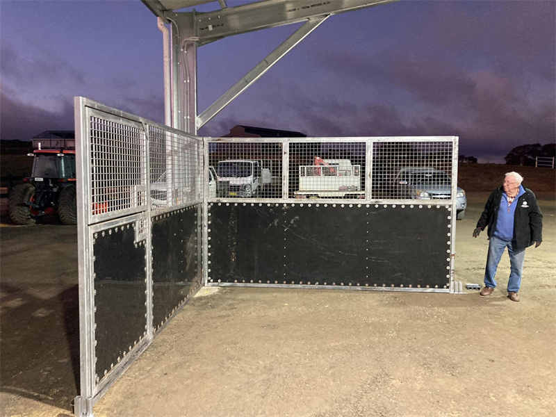
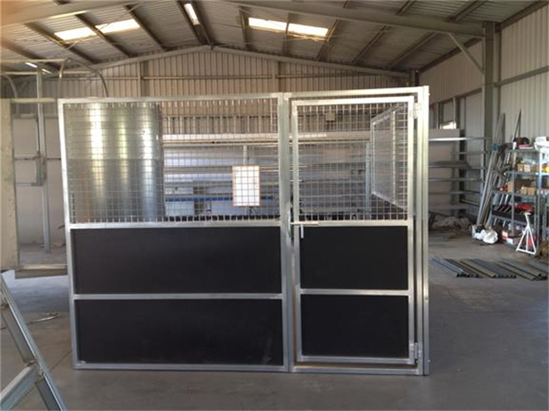
- Step 6 — Wall Panels: Install HDPE wall panels between corner posts, working from bottom to top. Each panel has a serial number embossed on the interior face that corresponds to a bay position on the installation chart.
- Step 7 — Intermediate Uprights and Top Rail: Only after all wall panels are seated do you install the intermediate uprights and the continuous top rail that runs the perimeter.
- Step 8 — Roof Trusses Last: With the entire wall structure bolted, squared, and tensioned, lift the pre-assembled truss sections onto the top rail brackets. The truss shoes have matching pre-drilled guide holes — again, locating pins before bolts.
- Step 9 — Skylight and Roof Cladding: Fit skylight channels to the truss purlins. Lay HDPE roof sheets. Tighten roof fasteners to 12 N·m only — overtightening crushes the HDPE thermal expansion gap and causes buckling in summer.
Quad-Configuration Sequencing Differences
Back-to-back quad bays introduce a shared central wall and a continuous roof line. The critical sequencing difference is that the shared center wall uprights must be installed after both adjacent bays’ perimeter base frames are anchored and squared independently. Installing the shared uprights first — a common contractor shortcut — locks in any squareness discrepancy between the two bays, creating a compound racking stress that cannot be corrected later.
- Phase 1: Anchor and square both bays’ base frames independently. Cross-check the centerline where the shared wall will stand. The two inner base rails must be parallel within 2 mm over the full 7.2 m combined length.
- Phase 2: Erect all four external corner posts and the outer wall panels for both bays. Leave the center wall channel empty.
- Phase 3: Install the shared center uprights and center wall panels, bolting into the pre-drilled brackets on both sides simultaneously. The color-coded fastener bags for quad kits include an additional Bag C (yellow) specifically for center-wall connections.
- Phase 4: Run continuous top rails across the full span including the center section. Only then proceed to roof truss installation as a single connected roof plane.
Pre-Drilled Guide Holes: The DB Standard That Eliminates On-Site Drift
Walk onto any installation site where a generic imported stable kit is being assembled and you’ll see the same scene: a contractor with a cordless drill, punching fresh holes through galvanized brackets because the pre-drilled holes don’t line up. Every new hole removes the 42-micron zinc coating from the bore wall, exposing raw steel. In a coastal NZ environment, that drilled hole becomes the initiation point for galvanic corrosion within 18 months. The zinc around the hole sacrifices itself to protect the exposed steel, and you get classic white rust blooming from every field-drilled connection.
DB Stable’s manufacturing standard eliminates this entirely. Every bracket, upright base plate, and truss shoe is CNC-drilled in the factory before the hot-dip galvanizing bath. The 42-micron zinc layer coats the interior of every bolt hole uniformly, creating a complete corrosion envelope. The holes are positioned with a positional tolerance of ±0.3 mm relative to the matching panel insert. In practice, this means the supplied locating pin slides through without resistance when — and only when — the frame members are correctly aligned. If a pin binds, the frame is not square. It’s a built-in quality checkpoint that requires no measuring tools and no skill to interpret.
This is not a minor convenience feature. It directly prevents the two failure modes that dominate warranty claims on competitor kits: mixed-metal corrosion from field-drilled holes that strip the galvanic protection, and progressive frame misalignment from panels that were bolted up 3 mm out of position and then loaded with roof weight. When you’re specifying stables for a 30-horse facility with a 15-year operational horizon, the presence or absence of factory pre-drilled guide holes is the difference between a structure that stays square through a decade of nor’easter storms and one that needs $3,000 in frame straightening and re-cladding by season five.

Conclusion
Most installation failures trace back to two things: an unlevel base and mixed-metal fasteners that start corroding before the first season ends. Getting this right means your stables resist 10 kN uplift loads during a Category D cyclone, keep horses safe from exposed bolt edges, and hold their structural alignment for a decade. You are not buying panels — you are buying the 10 years of operational uptime that a proper assembly sequence and 42-micron galvanized frame deliver.
If you want to audit your current build plan or see how pre-drilled, serialised kits eliminate the alignment errors that trigger warranty disputes, review the full system specifications. The product gallery shows exactly how each bay ships — right down to the colour-coded fastener bags — so your next installation runs without the $2,500 rework bill.
Frequently Asked Questions
Ground prep for flat-pack stables?
Begin with a level, compacted base—ideally a 100–150mm crushed rock or gravel pad extending 300mm beyond the stable footprint—to ensure drainage and prevent settling. Avoid soft soils or grass directly under the structure, as they retain moisture and compromise the frame’s stability. For ANZ conditions, incorporate a slight fall away from the stable and confirm the ground is free of tree roots or debris that could distort the hot-dip galvanized steel base rails over time.
Common assembly mistakes?
The most frequent error is failing to square the base frame before tightening fasteners, causing cascading alignment issues with HDPE wall panels and roof beams. Another is installing the 10mm UV-resistant HDPE boards under direct sun without allowing for their negligible thermal movement—unlike other materials, DB Stable’s boards don’t expand significantly, but forcing tight seams can still stress connections. Skipping the pre-sorted hardware check or ignoring the sequential panel numbering also leads to rework, delaying assembly and compromising the structure’s engineered fit.
Gaps between panels after install?
Persistent gaps typically come from an unlevel base or a racked frame, not the panel dimensions themselves, as our panels are CNC-cut to tight tolerances. If the galvanized steel frame isn’t perfectly square and the base plates aren’t fully seated on solid ground, panel edges can’t lock flush. In coastal sites, minor initial gapping may also appear if anchor bolts are over-torqued before the structure settles; our 42-micron hot-dip galvanized frame maintains its shape, but the foundation must be corrected first.
Rust prevention for coastal bolts?
Specify hot-dip galvanized or 316 stainless steel fasteners from the start—our standard kit hardware includes a corrosion-resistant coating exceeding 42 microns, matching the frame’s 10-year lifespan. In aggressive salt-spray zones, apply a cold galvanizing compound to bolt threads during assembly and schedule a bi-annual wash-down with fresh water to remove chloride build-up. Avoid mixing metals; pairing our rust-free aluminium swivel feeders with incompatible fasteners can create galvanic corrosion, so always use the supplied dedicated bracket hardware.
Damaged stable part on arrival?
Document the damage with clear photos of the component and its packaging, then contact our support team immediately via the quick quote link or your dedicated project expert—we maintain replacement stock in Oceania for rapid dispatch. Do not attempt to bend or weld galvanized parts on site, as this compromises the 42-micron zinc layer and voids the 10-year frame warranty. We will arrange a no-cost replacement part and guide you on any adjusted assembly sequence to keep your installation on track without compromising integrity.